
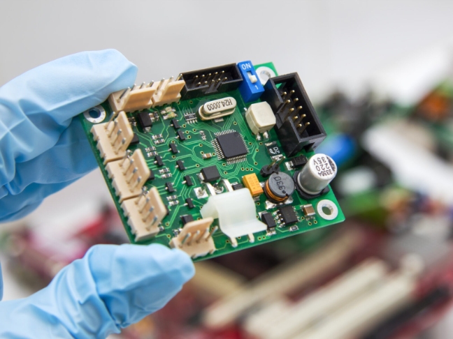
High FrequencyPcB

Jinhua has been doing high-frequency pcb with over 13 years
Typicallyin range from 500MHz to 2GHz
JH PCBA Rigid-Flex PCB
Mature different kind HF material mixed lamination technology: FR4+PTFE,FR4+408HR,FR4+ROGERS
3mil/3mil min trace w/s, impedance control tolerance within ±8%
Materials available: rogers, Shengyi, taconic, teflon, arlon, etc.
What is High Frequency (HF) PCB?
High Frequency (HF) PCB is that kind special circuit boards with high frequency > 1GHz, with relative high purchase price. The physical properties, precision, technology parameters requests of high frequency PCB is quite high, normally used in cars collision avoidance system, satellite system, 5G base station communication devices etc fields.
Keep them in mind when choosing high frequency PCB
Dielectric constant(Dk): DK should be small and stable enough, usually the smaller the better, high DK may lead to signal transmission delay.
Dissipation Factor(Df): DK should be small and stable enough, usually the smaller the better, high DK may lead to signal transmission delay.
Coefficient of thermal expansion: The Coefficient of thermal expansion should be the same with copper foil as much as possible because the difference will lead to copper foil separated in the changes of cold and heat.
Moisture Resistance: Moisture absorption must be low, or will result in Dk and Df loss when in a wet environment.

High quality material as high quality guarantee basis
Establish strategy long time partnership cooperation with famous material manufacturers, such as Rogers, Shengyi, Taconic, Teflon, Arlon, etc.
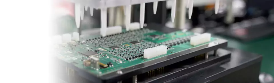
Equipped with full manufacturing equipment for communication industry PCB
Plasma desmear machine and VCP plating line to provide excellent uniformity of barrel copper thickness and high consistency of impedance value.


Exquisite technology to meet high quality communication PCBs request
- Mature different kind HF material mixed lamination technology: FR4+PTFE,FR4+408HR,FR4+ROGERS
- 3mil/3mil min trace w/s, impedance control tolerance within ±8%
Professional technology engineers good at the details how to control HF PCB good quality
- Before solder mask, HF boards can’t be scrubbed, or will leads to poor adhesive force, so micro-etch by chemicals is the best way of coarsening.
- Most material of HF PCB are PTFE, using normal milling cutter will cause much tiny burrs, so we use special double edged milling cutter to guarantee slot size tolerance±0.1mm and prevents tiny burrs.
- The impedance control and trace width/spacing requests of HF PCB is quite strict, the tolerance just about 2%.
- The copper adhesive force is not ideal because high frequency material special features when PTH process, so before PTH, all vias and boards surface need coarsening preprocessing by using plasma and so on advanced equipment to improve PTH hole copper and solder mask adhesive force.


Capability of High Frequency PCB
| Feature | Capability |
|---|---|
| Layer Counts | 1-36 |
| Normal Lead Time | 4-6 Working Days |
| Fast Lead Time | 1-2 Working Days |
| Materials | ISOLA, Shengyi, Rogers, Nelco, Arlon etc. |
| Copper Thickness(Finished) | 1/3OZ-20OZ |
| Overall Board Thickness | 0.2-5MM |
| Minimum Line/Track Width & Space | 3Mil/3Mil |
| Solder Mask Color | Green,black,blue.white, red,yellow. glossy and matt etc. |
| Legend/Silkscreen Color | White, yellow, black, etc |
| Back drilling | ≤16mil |
| Surface Treatment | Plating Gold, ENIG, Immersion Tin&Silver etc. |
| Qualifications | UL, ISO 14001:2015 IS9001:2015Certified |

Material for High Frequency PCB
| Material for high frequency boards | Order share | εr, Dk- Permittivity |
Dk Loss Tangent |
Tg | Td Value | Thermal conductivity |
CTE-z (T < TG) | Electric Strength |
Surface Resistivity |
Peel Strength |
|---|---|---|---|---|---|---|---|---|---|---|
| @10GHz | @10GHz | °C | °C | W/m*K | ppm/°C | KV/mm | MΩ | >N/mm | ||
| Rogers 4350B HF Material |
+++ | 3,5 | 0,0037 | 280° | 390° | 0,69 | 32 | 31 | 5,7 x 10^9 | 0,9 |
| Rogers 4003C PTFE HF Material |
++ | 3,4 | 0,0027 | 280° | 425° | 0,71 | 46 | 31 | 4,2 x 10^9 | 1,1 |
| Panasonic Megtron6 HF Material |
+ | 3,6 | 0,004 | 185° | 410° | – | 45 | – | 1 x 10^8 | 0,8 |
| Rogers RO3003 PTFE ceramic-filled |
+ | 3,0 | 0,0013 | – | 500° | 0,50 | 25 | – | 1 x 10^7 | 2,2 |
| Rogers RO3006 PTFE ceramic-filled |
o | 6,2 | 0,002 | – | 500° | 0,79 | 24 | – | 1 x 10^5 | 1,2 |
| Rogers RO3010 PTFE ceramic-filled |
o | 10 | 0,0022 | – | 500° | 0,95 | 16 | – | 1 x 10^5 | 1,6 |
| Taconic RF-35 Ceramic |
o | 3,5** | 0,0018* | 315° | – | 0,24 | 64 | – | 1,5 x 10^8 | 1,8 |
| Taconic TLX PTFE |
o | 2,5 | 0,0019 | – | – | 0,19 | 135 | – | 1 x 10^7 | 2,1 |
| Rogers RO3001 Bonding Film for PTFE |
– | 2,3 | 0,003 | 160° | – | 0,22 | – | 98 | 1 x 10^9 | 2,1 |
| Taconic TLC PTFE |
– | 3,2 | – | – | – | 0,24 | 70 | – | 1 x 10^7 | 2,1 |
Construction examples for High Frequency PCB


High Frequency PCB Main Application:

High Frequency

High Frequency

High Frequency

High Frequency
High Frequency
High Frequency
High Frequency
High Frequency
Feature: 2L RO4003C, Dk of 3.38+/-0.05, Dissipation factor of 0.0027 at 10 GHz, Thermal conductivity 0.71 W/M.K
Low Z-axis coeffcient of thermal expan-sion at 32 ppm/’℃
Application: lP Infrastructure
Feature: 2L RO3210, Dk of 10.2+/-0.30, Dissipation factor of 0.0027 at 10 GHz, Thermal conductivity 0.61 W/M.K
Application: Wireless telecommunications systems
Feature: RT/Duroid® 5880, Dk of 2.20+/-0.02, Dissipation factor of 0.0009 at 10 GHz, Thermal conductivity 0.20 W/M.K, Low moisture absorptionIsotropic
Application: 5G communication system
Feature: 2LRO4350B, Dk of 3.48+/-0.05, Dissipation factor of 0.0037 at 10 GHz, Thermal conductivity 0.69 W/M.K, Low Z-axis coefhcient of thermal expansion
Application: Communications system
